
Page 23 - 2.1 Ein-Abstech-System RC / 2000
P. 23
Technische Informationen für das Axialeinstechen
Technical information for axial grooving
Auswahl des Durchmesserbereiches „DB“ bei Axialunterstützblättern.
– Bei der Auswahl des Durchmesserbereiches ist grundsätzlich der Außen-Ø der Nute maßgebend!
– D. h. der 1. Einstich muss innerhalb des angegebenen Durchmesserbereiches „DB“, bezogen auf
den Nut-Außen-Ø liegen.
– Beispiel: DB 75-100
Der 1. Einstich muss im Bereich von Nut-Außen-Ø 75 und 100 erfolgen!
– Grundsätzlich kann nach dem 1. Einstich, jeweils um ca. 2/3 der Stechbreite (ST-B), sowohl bis zur
Drehmitte als auch bis theoretisch unendlich, versetzt eingestochen werden.
Werkzeugposition
– Beim axialen Einstechen ist eine Werkzeugposition - Überkopf- vorzuziehen, da ein wesentlich
günstigerer Spanablauf möglich ist (die Späne fallen durch die Schwerkraft nach unten in die Spänewanne bzw. Späneförderer).
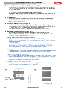
Auskammern (Schnittaufteilung / siehe Bild 1)
– Bei dieser Bearbeitung erfolgt der 1. Einstich am größtmöglichen Außen-Ø der Nute (abhängig vom
Durchmesserbereich des vorhandenen bzw. gewählten Axial-Unterstützblattes); danach erfolgt der
2. Einstich - versetzt um ca. 2/3 der Stechbreite - in Richtung Drehmitte, usw.
– Diese Arbeitsweise sollte bevorzugt auch bei größeren Stechtiefen angewandt werden!
Ausstechen von Scheiben und Kernen (siehe Bild 2)
– Beim Ausstechen von Scheiben oder Kernen ist unbedingt darauf zu achten, dass ein
Verbindungssteg erhalten bleibt - niemals durchstechen! Die Scheibe oder der Kern muss nach dem axialen Einstechen separat ausgepresst werden.
Selection of the diameter range for axial support blades
– By the selection of the diameter range, the groove outside diameter is decisive!
– That means, the first recess has to be within the specified diameter range „DB“, in reference to the
groove outside diameter.
– Sample: DB 75-100
The first recess has to be ensuing in the range of the groove outside diameter 75 and 100!
– Basically, after the first recess is done, the following recesses can be made by moving the tool
about 2/3 of the width of cut, both to the center line as well as theoretical endless.
Tooling setup
– By the axial recessing, a tool position - overhead - should have priority because the escape of chips
is essential better (due to gravity, the chips drop down into the chip tray or chip conveyor).
Trepanning (cut Sharing / see to picture 1)
– In this machining, the first recess ensues at the maximum diameter of the groove (depending on the
diameter range of the available, respectively choosed axial-support blade); afterwards, the second
recess can be done by moving the tool about 2/3 of the cutting width in direction of the centerline.
– Larger cutting depths should also favor this method of operation!
Recessing of discs and cores (see to picture 2)
– In this operation it is absolutely necessary that a connection gab remains- never cut through! The
disc or core must be press out separately after the axial cutting.
Bild
2
Bild 2
picture 2
picture 2
0208
ZINNER GmbH - Präzisionswerkzeuge 23
