
Page 13 - 4.7 ISO-Gewindeprogramm
P. 13
Technische Informationen
Technical information
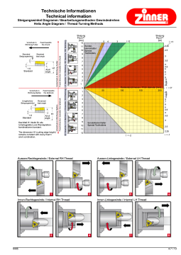
Steigungswinkel Diagramm / Bearbeitungsmethoden Gewindedrehen Helix Angle Diagram / Thread Turning Methods
®
ί =1
3.5
4 4.5 5
6
7
9 11 14 18 24
Vorschub in Richtung Futter
Feed towards the chuck
2.25 2.5
3
Steigung Pitch P* [mm]
12 11 10
54 3 ί=2
Steigung Pitch P* [tpi]
So
nder- klemmhalter
Special Toolholders
Flank
endurchmesser / Pitch diameter [mm]
50
100
150
200
Sonderklemmhalter Special Toolholders
Standard Steigungswinkel
1.5
Standard
Vorschub in Richtung Spitze
9 8 7 6 5 4 3 2
1
Standard lead angle
Anvil angle
H1
0
ί = 0°
24 18 14 11
7
6
5 4.5
Feed towards the tailstock
1
2 39
Umgekehrter Steigungswinkel
1.5 Standard
Reversed lead angle
Anvil angle
4 5 6
H17 4 3.5
8
9 10 11 12
Das Maß H1 bleibt für alle Unterlegplatten und Wendeplatten- kombinationen konstant.
The dimension H1 (cutting edge height) remains constant with every insert / anvil combination.
Aussen-Rechtsgewinde / External RH Thread
ί = -2
Aussen-Linksgewinde / External LH Thread
3 2.5
2.25
ί = -1
Innen-Rechtsgewinde / Internal RH Thread
Innen-Linksgewinde / Internal LH Thread
1
2
3478
0405 4.7 / 13
5
6
β
-β
Vorschub in Richtung Spitze Vorschub in Richtung Futter
Feed direction towards the tailstock Feed direction towards the chuck
RH Gewinde / LH Werkzeug LH Gewinde / RH Werkzeug LH Gewinde / LH Werkzeug RH Gewinde / RH Werkzeug
